
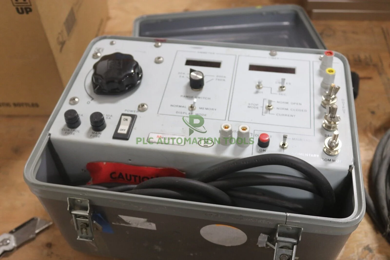
Megger MS-2-230 High Current Test Set
Megger MS-2-230 High Current Test Set
- Genuine Product
- Technical Support
- Worldwide Shipping
Up for sale a used Megger MS-2-230 High Current Test Set Unit. This item fully operational and functions as intended. Comes with a 3-month warranty and 30-day money-back guarantee.
Megger MS-2 is a self-contained test set that incorporates a variable high-current output and appropriate control circuitry and instrumentation for testing thermal, magnetic or solid-state motor overload relays; molded-case circuit breakers; and ground-fault trip devices.
Megger MS-2 is capable of testing the time-delay characteristics of motor overload relays and molded-case circuit breakers rated up to 125 amperes, when following the recommended test procedure of testing the time delay of these devices at three times their rating.
Higher currents are available for the short durations required to test an instantaneous trip element. For example, the test set will provide a maximum shortduration output of 750 amperes through a typical, 125 ampere, molded-case circuit breaker.
Additional applications include verifying the ratio of current transformers and testing panelboard ammeters and voltmeters
FEATURES AND BENEFITS
- Rugged and lightweight: Unit weighs only 33 lb (15 kg) and is tough enough to withstand daily field or plant use.
- Digital memory ammeter: High accuracy, direct-reading instrument has read-and-hold memory for measurement of shortduration currents. Ideal for testing ground fault devices, overcurrent relays and molded-case circuit breakers.
- Digital, multirange timer: Crystal-controlled, high-accuracy instrument with autoranging measures operating time to 1 millisecond.
- High-current output: Provides instantaneous currents up to 750 amperes through a 125 ampere breaker in a small 33lb (15kg) package.
Megger MS-2 Specifications
| Input | |||||||||||||
| Input Voltage | 230V | ||||||||||||
| Frequency | 50/60 Hz | ||||||||||||
| Phase | 1f | ||||||||||||
| Output | |||||||||||||
| Output Ranges | The output is continuously adjustable in four ranges to accommodate a variety of test-circuit impedances: 0 to 5 A at 120 V max. 0 to 25 A at 24 V max. 0 to 120 A at 6 V max. 0 to 240 A at 3 V max. |
||||||||||||
| Output Capacity | The output circuit is designed to permit shortduration overloads and the output ranges will provide several times their current rating, provided the output voltage is sufficient to push the desired current through the impedance of the test circuit. | ||||||||||||
| Time-Delay Test Capability | Devices rated up to 125 A using a test current of three times rating, 375 A | ||||||||||||
| Instantaneous Trip Test Capability | 750 A through a typical 125 A molded-case circuit breaker connected with the supplied test leads | ||||||||||||
| Overload Capability |
|
||||||||||||
| Output Initiate Circuit | The test set uses a solid-state output initiating circuit. To increase reliability and eliminate contact maintenance, this circuit uses a triac instead of a contactor to initiate the output. The initiating circuit provides momentary and maintained modes to control output duration. The momentary mode is used whenever the output is to be on for a short duration, such as when performing instantaneous trip tests, or to avoid damage or overheating of the device under test while setting the test current. In the maintained mode, the output remains energized until manually turned off or, when performing timing tests, until the device under test operates — which both stops the timer and de-energizes the output. |
||||||||||||
| INSTRUMENTATION - Ammeter | |||||||||||||
| Operating Modes (switch-selected) | Memory; Normal | ||||||||||||
| Display | 3.5 digit, extra-bright LED display with 0.3 in. (7.62mm) numerals | ||||||||||||
| Ranges (switch-selected) | 0 to 1.999/19.99/199.9/750 A | ||||||||||||
| Continuous Accuracy (overall ammeter system) | ±1% of reading, ±1 digit on three high ranges | ||||||||||||
| ±1% of range, ±1 digit on low range | |||||||||||||
| INSTRUMENTATION - Timer | |||||||||||||
| Display | 5-digit, extra-bright, LED display with 0.3 in. (7.62mm) numerals | ||||||||||||
| Ranges (switch-selected) | 0 to 99.999 s | ||||||||||||
| 0 to 999.99 s | |||||||||||||
| 0 to 99999 cycles | |||||||||||||
| Accuracy | ±0.005% of reading, ±1 digit | ||||||||||||
| Timer Control Circuit | |||||||||||||
| Timer Start / Stop | Automatically starts when output is energized; automatically stops timer and de-energizes output when the device under test operates | ||||||||||||
| Current Actuated | Thedevice that has no auxiliary contacts to monitor, such as a single-pole circuit breaker. The timer stops when the output current is interrupted. | ||||||||||||
| Normally Closed | The timer stops and the output is de-energized when the contacts open. | ||||||||||||
| Normally Open | The timer stops and the output is de-energized when the contacts close. | ||||||||||||
| Physical | |||||||||||||
| Enclosure | High strength, molded, suitcase-type enclosure with carrying handle and removable cover. Storage space is provided for test leads | ||||||||||||
| Standards | CE; EN 61326-2-1; EN 61010-1; EN 61010-031 | ||||||||||||
| Dimensions (H x W x D) | 457.2 x 241.3 x 342.9 mm | ||||||||||||
| Weight | 15 Kg (33 lbs) | ||||||||||||